
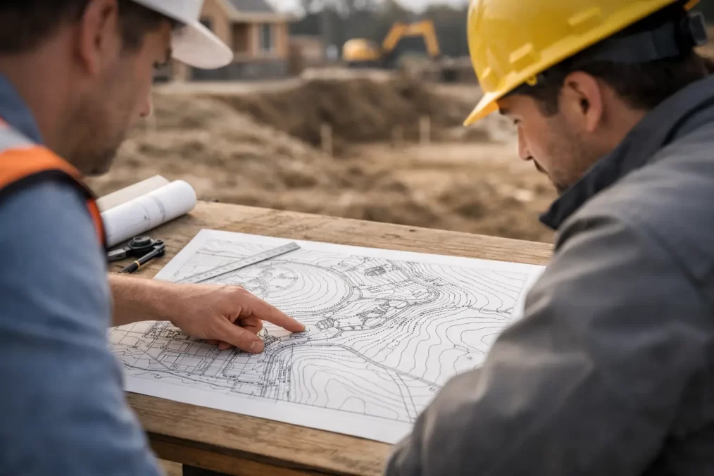
How to Read Contour Plans on a Building Site
A contour plan can tell you far more than whether a block is “sloping”. It shows how the land rises and falls, where water is likely to move, and whether a proposed building, driveway or retaining wall may need more work than expected. Knowing how to read contour plans helps property owners and project teams make better decisions before design and construction costs start to build.
For a new home, extension, subdivision or civil works project, the contour plan should be read alongside the survey legend, boundary information and any proposed design levels. It is not a substitute for engineering or architectural advice, but it gives every project stakeholder a reliable starting point.
Start with what the plan is showing
A contour plan is usually part of a detail and contour survey, also called a topographic survey. A registered surveyor measures the site and presents physical features such as buildings, fences, driveways, kerbs, trees, visible services, pits, walls and ground levels on a scaled drawing.
The contour lines are the key to understanding the landform. Each line connects points of equal elevation. If a contour is labelled 12.0, every point on that line is at an elevation of 12.0 metres relative to the plan’s nominated datum.
Before interpreting the levels, check the title block and legend. These typically identify the survey date, plan scale, contour interval, level datum and survey notes. The north point is also essential. It helps you understand orientation, solar access and the likely direction of drainage when considered with the levels.
Survey information reflects conditions observed at the time of survey. A site that has since been excavated, filled, cleared or built upon may no longer match the plan exactly. This matters on active construction sites and properties that have changed hands or undergone previous works.
Understand the contour interval
The contour interval is the vertical difference between adjacent contour lines. On many residential plans, contours may be shown at 0.2-metre or 0.5-metre intervals. A plan with contours labelled 10.0, 10.5 and 11.0 has a 0.5-metre interval.
Do not assume the interval from the appearance of the drawing. A 0.5-metre change in elevation can look dramatic on a short block and barely noticeable across a large rural site. Read the stated interval first, then use the labels to confirm whether land is rising or falling.
Intermediate contours are often lighter or unlabelled, while index contours may be darker and labelled at wider intervals. For example, between a labelled 10.0 contour and 11.0 contour, there may be four finer lines representing 10.2, 10.4, 10.6 and 10.8 metres. The legend should remove any doubt.
Read the direction and steepness of the fall
Contour numbers increasing across the site mean the ground rises in that direction. Numbers decreasing mean it falls. This simple check is the foundation for understanding a block.
The spacing between lines shows the steepness of the terrain. Closely spaced contours indicate a steep slope because the ground changes height quickly over a short horizontal distance. Widely spaced contours indicate gentler land. Where contours are almost parallel and evenly spaced, the site generally has a consistent fall. Curving, irregular lines can reveal ridges, drainage lines, benches and local hollows.
A contour plan does not always show the exact grade at a glance. To estimate it, compare the vertical level change with the horizontal distance measured using the plan scale. A fall of 1 metre over 20 metres is a 5 per cent gradient. For accurate driveway grades, accessible paths, drainage design or earthworks quantities, designers should work from the survey data and calculate the required levels rather than relying on a visual estimate.
Spot levels provide the detail between contours
Spot levels are individual surveyed elevations, commonly shown as a number beside a small cross, point or feature. They are particularly valuable at building corners, kerb lines, driveway edges, floor levels, pits, retaining walls and changes in surface material.
Contours describe the general shape of the land. Spot levels show the precise elevation at a particular surveyed point. If you are considering an extension near an existing house, spot levels around the slab, threshold and adjoining ground can help the designer assess step-downs, stormwater paths and finished floor level options.
Pay attention to abbreviations. Existing finished floor levels, kerb levels, gutter levels, ridge levels and invert levels may all appear on a plan. They are not interchangeable. An invert level is the level at the bottom inside a drainage pipe or pit, while a finished floor level refers to the completed internal floor surface. Confusing these figures can lead to incorrect drainage or construction assumptions.
Check the datum before comparing levels
Most contemporary survey plans in NSW reference levels to Australian Height Datum, often abbreviated to AHD. This provides a common vertical reference point, allowing consultants to compare levels across survey, engineering and architectural documents.
However, some older plans or limited site sketches may use an assumed datum. An assumed datum is a local reference chosen for that specific job, such as 100.00 at a nominated point. It can be useful for relative design work, but it should not be compared directly with AHD levels unless the relationship between the two datums is known.
This is especially relevant for coastal and waterfront properties, flood planning, connection to public drainage and projects where proposed levels must be coordinated with council or engineering information. A level of 5.20 on one drawing may not mean the same thing as 5.20 on another.
Use contours to understand drainage, not to design it
Water generally travels downhill, crossing contours at approximately right angles. By following the lower numbers, you can identify the likely broad direction of surface flow across the site.
A valley or drainage line often appears where contour lines form a pointed shape that faces uphill. A ridge is the opposite: contour lines bend downhill around higher ground. These patterns can influence where runoff concentrates during heavy rain, where stormwater collection may be needed, and where cut or fill may create new drainage issues.
Existing drainage pits, swales, table drains and kerb inlets should also be located on the survey where visible. Their presence does not confirm capacity, legal point of discharge or approval for a new connection. A hydraulic engineer or suitably qualified designer may need to assess those questions, particularly where a development changes roof area, paving or site levels.
On the Central Coast, this early assessment is valuable on sloping, bushland and coastal sites where runoff, rock, retaining requirements and access can affect the feasibility of a design. A modest-looking fall on paper can become a significant construction consideration once driveway gradients, stormwater discharge and usable outdoor space are factored in.
Separate existing ground from proposed design levels
A contour survey records existing conditions. It does not tell you where a new building should sit or how a site should be regraded. Proposed levels are normally shown on architectural, civil or structural drawings and may include finished floor levels, pavement levels, retaining wall heights and proposed contours.
When comparing documents, identify whether each notation is existing or proposed. Existing contours are often shown as solid or lighter lines, while proposed levels may be dashed or given a separate colour in digital plans. The drawing legend controls this, so do not rely on drafting conventions alone.
The difference between existing and proposed ground levels indicates potential cut and fill. Small changes may be manageable, while larger changes can affect retaining walls, spoil removal, service connections, access, neighbour impacts and approval requirements. The best outcome is not always the design with the least excavation. It depends on drainage, soil conditions, building form, bushfire constraints, access and the applicable planning controls.
Do not mistake a contour plan for a boundary plan
A detail and contour survey often shows boundaries for design reference, but the purpose and certification of the plan matter. If a fence, wall or building is close to a boundary, do not assume the visible occupation marks the legal boundary position.
For fencing disputes, building near a boundary, title matters, encroachments or subdivision work, a cadastral survey or identification survey may be required. Those services involve examination of title evidence and field work to determine or verify boundary position. Contours cannot resolve a boundary question.
Common errors when reading contour plans
The most costly errors usually come from treating one piece of plan information as if it answers every question. Avoid assuming that contours show legal boundaries, that a nearby pit guarantees stormwater connection, or that a single spot level represents the whole building area.
Also check the date of survey, scale and notes before sending the plan to a designer or builder. Enlarging a PDF does not make dimensions more accurate, and a photo of a plan can lose critical legend information. If the site has substantial vegetation, dense undergrowth, inaccessible areas or recent earthworks, ask whether further survey work is needed before finalising design levels.
How to read contour plans with confidence
A well-prepared contour plan gives architects, engineers, builders and owners a shared picture of the site. Start with the contour interval and datum, establish which way the site falls, then use spot levels and visible drainage features to understand the areas that need closer attention.
If the plan raises questions about floor levels, driveway grades, retaining, drainage or boundaries, resolve them before committing to a design. Early discussion with a registered surveyor can turn an uncertain block into clear, usable information for the consultants who need to move the project forward.